
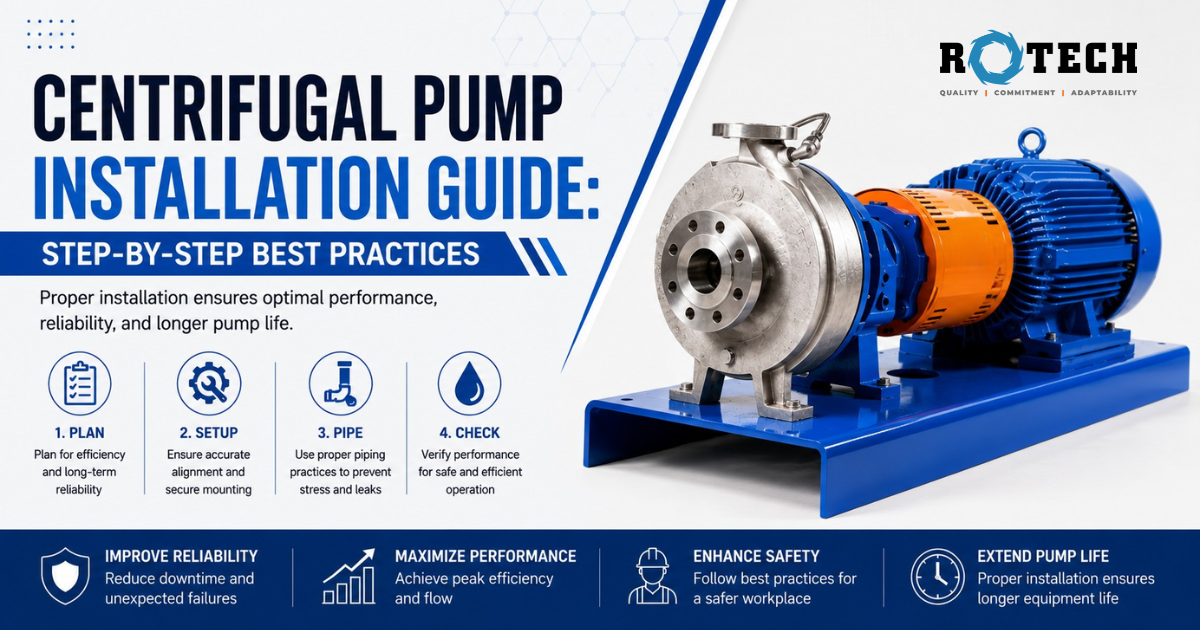
A centrifugal pump installation has eight stages — site and foundation preparation, baseplate mounting and grouting, pump and motor positioning, shaft alignment, piping connections, electrical connections, priming, and startup checks. Every stage affects performance and reliability. Skipping or rushing any one of them is the most common cause of premature pump failure.
A centrifugal pump is only as good as its installation. You can specify the right pump, choose the right materials, select the right seal — and still end up with a pump that vibrates, leaks, cavitates, or fails within months if the installation is done poorly.
Poor shaft alignment alone accounts for more than 50% of premature pump failures in industrial service, according to the Hydraulic Institute. Add poor piping practice, incorrect grouting, or inadequate priming to the mix, and you have a pump that will cost far more in maintenance and downtime than it should.
This guide covers every stage of centrifugal pump installation correctly, in the right order, with the detail that most installation guides skip. It applies to horizontal end-suction pumps, ANSI process pumps, and frame-mounted chemical process pumps across industrial, chemical, and water treatment applications.
For background on how centrifugal pumps work before you install one, see our complete guide to centrifugal pumps.
Table of Contents
- Pre-Installation Checklist
- Site and Foundation Preparation
- Baseplate Mounting and Grouting
- Positioning the Pump and Motor
- Shaft Alignment — The Most Critical Step
- Suction and Discharge Piping
- Electrical Connections
- Priming the Pump
- Startup and Commissioning Checks
- Post-Startup Monitoring
- Common Installation Mistakes
- Installation Checklist
- Frequently Asked Questions
1. Pre-Installation Checklist
Before anything goes into the ground or onto a baseplate, three things need to happen.
Read the manufacturer’s installation manual. Every pump manufacturer publishes installation, operation, and maintenance (IOM) documentation specific to their pump model. The IOM specifies foundation loads, alignment tolerances, piping connection sizes, allowable flange loads, lubrication requirements, and startup procedures. Generic installation guides, including this one, provide the framework. The IOM fills in the model-specific numbers.
Inspect the pump on delivery. Check for shipping damage before signing the delivery receipt. Rotate the shaft by hand to confirm it turns freely and smoothly — any roughness, grinding, or resistance indicates an internal problem that needs to be addressed before installation, not after. Confirm all components are present against the packing list.
Confirm the pump matches the specification. Check that the pump model, impeller diameter, materials of construction, seal type, and mechanical seal material all match the original purchase specification. A pump installed in the wrong material for the chemical it will handle is a safety and reliability issue that is far harder to fix after grouting and piping than before.
2. Site and Foundation Preparation
Foundation Requirements
A centrifugal pump foundation does three things: it absorbs vibration, it prevents movement under operating loads, and it provides a stable, level surface that holds alignment through temperature changes and long-term settling.
The standard recommendation from the Hydraulic Institute is that a pump foundation should weigh at least three to five times the combined weight of the pump, motor, and baseplate assembly. For most industrial installations, this means a reinforced concrete pad.
Foundation specifications to check:
- Level to within 3 mm per metre in all directions before the baseplate goes down
- Anchor bolt positions set to match the baseplate layout drawing precisely
- Concrete fully cured before baseplate installation (typically 28 days for new pours, though early-strength mixes reduce this)
- Top surface clean and free of oil, grease, laitance, and loose material before grouting
For pump installations on structural steel frames — elevated platforms, mezzanines, offshore structures — the frame stiffness and natural frequency need to be checked against the pump’s operating speed to avoid resonance. This is an engineering calculation, not a field judgment call.
Anchor Bolts
Set anchor bolts to the pump’s baseplate drawing, not to a generic spacing. Bolt size, projection height, and sleeve diameter all matter. Anchor bolts set incorrectly are difficult to correct after concrete placement. Use a template from the baseplate itself rather than measuring from a drawing if there is any uncertainty.
3. Baseplate Mounting and Grouting
Setting the Baseplate
Place the baseplate on the foundation using shims at the four corners and at intermediate points under the pump and motor pads. Shims allow you to level and adjust height without disturbing the foundation, and they remain in place permanently as the lower support surface under the grout.
Level the baseplate using a precision machinist’s level placed on the pump mounting pads — not on the baseplate edges, which may not be machined. Target levelness within 0.05 mm per metre (0.0006 in/ft) in both directions. This level of precision matters because a baseplate that is not level causes soft foot conditions and makes shaft alignment impossible to hold.
Finger-tighten anchor bolts at this stage. Do not torque them down until after grouting has cured.
Grouting
Grouting fills the space between the baseplate and the foundation, transfers pump and motor loads into the concrete, dampens vibration, and prevents the baseplate from moving. Done correctly, it locks the installation permanently and protects alignment. Done poorly, it introduces void spaces that allow the baseplate to flex under operating loads — which means your alignment shifts every time the pump starts.
Epoxy grout vs. cementitious grout: For industrial pump installations, especially in chemical and process service, epoxy grout is the standard. It is stronger, more chemically resistant, and produces less shrinkage than cementitious grout. Cementitious grout is acceptable for light-duty or non-process applications. Where the pump handles chemicals, confirm the grout is rated for any likely spill exposure.
Grouting procedure:
- Soak the concrete foundation surface with clean water 24 hours before grouting, then blow dry just before the pour. Dry concrete pulls moisture from the grout too quickly.
- Dam the baseplate perimeter to contain the liquid grout during placement.
- Pour grout from one side only, allowing air to escape from the other. Pouring from both sides traps air in the centre.
- Vibrate or rod the grout during placement to eliminate voids.
- Allow full cure before torquing anchor bolts or placing the pump load on the baseplate — typically 24 to 72 hours for epoxy grout depending on product and temperature.
After grouting and anchor bolt torquing, re-check the baseplate level. Some settling is normal. If the level has moved more than the tolerance allows, shim corrections may be needed before proceeding.
4. Positioning the Pump and Motor
Place the pump on the baseplate and align it to the pipe connections roughly before tightening mounting bolts. The pump’s suction and discharge flanges should be close to their final pipe positions, but do not make rigid piping connections yet. Connecting rigid piping before alignment locks the pump into a position that may not be optimal for alignment, and it introduces pipe strain into the equation before you can measure it.
Place the motor on the baseplate and connect it to the pump shaft with a spacer coupling — not the final coupling element yet. The spacer allows you to check and set alignment before the coupling halves are engaged.
Confirm the pump shaft rotates freely by hand with the coupling disconnected. Confirm the motor shaft does the same. Any binding indicates a problem to resolve before proceeding.
5. Shaft Alignment — The Most Critical Step
Shaft alignment is the single most important installation step. More centrifugal pump failures — bearing wear, seal failure, excessive vibration, coupling failure — trace back to misalignment than to any other installation factor.
The American National Standards Institute (ANSI) and the Hydraulic Institute both publish alignment tolerances for centrifugal pumps. The specific tolerance depends on pump speed — higher-speed pumps require tighter alignment than lower-speed ones.
Types of Misalignment
There are two types of shaft misalignment, and most real-world misalignment involves both simultaneously:
Angular misalignment — the shaft centrelines intersect at an angle. One coupling half is cocked relative to the other. The shafts are not parallel.
Parallel (offset) misalignment — the shaft centrelines are parallel but offset. They do not intersect. The pump and motor shafts are displaced from each other laterally or vertically.
Alignment Methods
Straight-edge and feeler gauge — the oldest method, still used for rough alignment checks. A straight-edge across the coupling outside diameters confirms whether offset alignment is grossly wrong. Not accurate enough for final alignment on any pump above low speed.
Dial indicator alignment — uses dial indicators mounted on the coupling to measure both angular and offset misalignment with rotation of the shaft. Suitable for most industrial pump installations and still widely used. Requires understanding of how to read and correct for both types of misalignment simultaneously.
Laser alignment — the current best practice for industrial pump alignment. A laser transmitter and receiver mounted on the coupling halves give real-time digital readout of misalignment in both planes, with correction vectors calculated by the system. Faster, more accurate, and less prone to reading errors than dial indicator methods.
Soft Foot
Before attempting final alignment, check for and correct soft foot. Soft foot occurs when one or more of the motor’s or pump’s mounting feet does not sit flat on the baseplate — it rocks slightly when the bolt is loosened. When the bolt is torqued, the casing distorts, which changes the internal geometry of the pump, affects seal and bearing loading, and means your alignment changes every time you tighten or loosen the mounting bolts.
To check for soft foot: with the pump and motor bolted down finger-tight, place a dial indicator on the coupling or shaft and loosen each mounting bolt one at a time. Movement greater than 0.05 mm (0.002 in) when a bolt is loosened indicates soft foot at that foot. Correct with precision shim stock under the low foot.
Alignment Tolerance
For pumps running at 3,000 RPM or less, the Hydraulic Institute recommends:
- Angular misalignment: no more than 0.05 mm/mm (0.05 inch per inch of coupling diameter)
- Parallel misalignment: no more than 0.05 mm (0.002 inch) total indicator reading
For higher-speed pumps, tolerances tighten further. Always refer to the specific manufacturer’s alignment tolerance for the pump and coupling being installed.
Re-check alignment after piping connections are made. Piping loads can shift alignment from the pre-piping condition. If alignment changes significantly after piping, it indicates pipe strain — covered in the next section.
6. Suction and Discharge Piping
The Rule That Most Installations Get Wrong
Pipe strain — the force a rigid piping system exerts on pump flanges — is one of the most common and most consequential installation errors in centrifugal pump practice. When piping connections pull, push, or twist pump flanges, they distort the casing, shift the impeller position relative to the wear rings, load the shaft bearings unevenly, and make it impossible to maintain alignment.
The Hydraulic Institute Standard ANSI/HI 9.6.2 specifies maximum allowable nozzle loads for centrifugal pumps. These are the limits within which the pump casing maintains its geometric integrity under piping loads. Exceeding them is not just a pump performance issue — it is a potential safety issue in chemical and process service where casing distortion can cause seal failure and chemical release.
The practical rule: pipe the system to the pump, not the pump to the pipe. The pump position is set by alignment. The piping should come to the pump flanges without being forced or strained. If the piping does not align naturally with the pump flanges after the pump is set, the piping needs to be adjusted — not the pump.
Suction Piping Best Practices
The suction side of a centrifugal pump is where most hydraulic problems originate. Poor suction piping design causes cavitation, air entrainment, uneven flow into the impeller, and suction recirculation — all of which reduce performance and shorten pump life.
Pipe diameter. The suction pipe should be at least one size larger than the pump’s suction nozzle, with a concentric or eccentric reducer at the pump inlet. For horizontal runs, use an eccentric reducer with the flat side up to prevent air pockets. For vertical runs, a concentric reducer is acceptable.
Suction pipe length. Keep the suction pipe as short and straight as possible. Every metre of suction pipe and every fitting adds friction loss that reduces available NPSH. Our guide on understanding NPSH and cavitation prevention explains how to calculate whether your suction pipe design leaves adequate margin.
No high points in the suction line. Any high point in the suction pipe where air or vapour can accumulate will disrupt prime and cause air entrainment during operation. Route the suction pipe continuously downhill from the source to the pump, with no loops or rises.
No throttling valves on the suction. Throttling the suction creates a pressure drop that reduces available NPSH and promotes cavitation. Control flow from the discharge side, never the suction side.
Straight run before the pump inlet. Provide at least five to ten pipe diameters of straight pipe immediately upstream of the pump suction nozzle. Fittings, elbows, and valves too close to the inlet create turbulence and swirl that disrupts flow into the impeller. This is especially important for double-suction pumps, where flow balance between the two impeller eyes is critical.
Foot valve and strainer (where a foot valve is used in flooded suction designs): size the foot valve for the full suction flow with minimal pressure drop. An undersized foot valve acts as a throttle on the suction and causes the same problems as a partially closed suction valve.
Discharge Piping Best Practices
Install a non-return (check) valve on the discharge to prevent backflow through the pump when it stops. Position the check valve between the pump discharge nozzle and the isolation valve.
Install a discharge isolation valve downstream of the check valve. This valve is used for controlled startup (start with valve closed or partially open) and for isolating the pump for maintenance.
Support discharge piping independently so it does not hang from the pump flange. Unsupported piping weight is a major source of pipe strain.
Include pressure gauges on both suction and discharge for operational monitoring and troubleshooting. See our guide on pump curves for centrifugal pumps for how to use pressure readings to confirm the pump is operating at its correct duty point.
For chemical service, all gaskets, flange bolts, and pipe materials must be compatible with the chemical — the same compatibility requirement that applies to the pump itself. See our chemical pump material compatibility guide for material selection by chemical type.
Final Alignment Check After Piping
After completing all piping connections, re-check shaft alignment with the coupling disconnected and all flanges bolted up. If alignment has shifted more than half the allowable tolerance from your pre-piping reading, the piping is exerting strain on the pump casing. Find and correct the strain source — typically a poorly supported pipe, a forced connection, or a flange that was not squarely aligned when bolted.
Do not proceed to startup with out-of-tolerance alignment after piping. The pump will vibrate, the seal will run hot, and bearing life will be significantly shortened.
7. Electrical Connections
Electrical connections must be made by a qualified electrician in accordance with local electrical codes and the motor manufacturer’s requirements. The following points are specific to centrifugal pump installations.
Verify motor rotation direction before coupling. This is a non-negotiable step that many installation teams skip. A centrifugal pump running backwards pushes a small amount of fluid in reverse through the impeller and generates almost no pressure. It looks like it is running. It sounds like it is running. It is not pumping. More critically, running a pump backwards with a closed or opening discharge valve can cause rapid pressure build-up in the wrong direction, which can damage the impeller and casing.
Check motor rotation by running it uncoupled (shaft free) for a moment and confirming the rotation arrow on the pump casing matches the motor direction. If they do not match, swap any two of the three power supply phases at the motor terminal box.
Thermal overload protection. Set the motor overload relay to the motor’s full load amperage as shown on the motor nameplate, then confirm that the actual current draw at operating conditions is within the motor’s rated range. A pump running significantly higher than expected amperage is operating at higher-than-designed flow, which indicates a system design issue — not a motor problem.
Earthing and bonding. Earth the pump and motor assembly to the facility earth grid. For pumps in hazardous areas (flammable or explosive chemical service), confirm earthing and bonding comply with the applicable hazardous area classification. OSHA 29 CFR 1910.303 covers general electrical safety requirements for industrial electrical installations.
8. Priming the Pump
A centrifugal pump must be primed before startup. Running a centrifugal pump dry — even for a few seconds — can damage the mechanical seal, which relies on a liquid film between its faces for lubrication and cooling. In chemical service, a dry-run seal failure means a chemical release.
Priming Methods by Installation Type
Flooded suction (pump below liquid level): Open the suction isolation valve and vent the pump casing through the vent plug or vent valve until liquid flows steadily and all air is expelled. This is the simplest and most reliable priming method.
Foot valve and suction lift: Fill the suction pipe and pump casing manually via the priming connection or vent port, using liquid from the discharge system or a separate supply. Confirm the foot valve is holding liquid before removing the fill source.
Self-priming pump: If a self-priming design was chosen for the application, confirm the priming chamber contains retained liquid before first start. See our self-priming chemical pump guide for how the automatic priming cycle works and what can go wrong with it.
Vacuum priming system: Some installations use a vacuum pump or ejector to evacuate the pump casing and suction line, drawing liquid up from the source. Confirm the vacuum system is rated for the chemical being handled and that all connections are leak-tight before drawing vacuum.
Priming Confirmation
Before starting, confirm:
- The pump casing is full of liquid with no air remaining
- The suction valve is fully open
- The discharge valve is closed or partially open (depending on the pump curve and startup procedure)
- No air pocket exists in any part of the suction line
9. Startup and Commissioning Checks
First Start Procedure
- Confirm all pre-start checks are complete — alignment, priming, motor rotation, lubrication, and all connections tightened.
- Open the suction valve fully.
- Start the motor with the discharge valve closed or partially open, depending on the pump’s minimum flow requirement and curve shape.
- Observe the pump as it comes up to speed. Normal startup is smooth and quiet. Any grinding, squealing, rattling, or banging means stop immediately and investigate before restarting.
- Slowly open the discharge valve as the pump reaches operating speed.
- Check the discharge pressure gauge. Compare the reading to the expected pressure at your operating flow rate from the pump curve. A reading significantly below expected at the rated speed indicates the pump is not developing the expected head — possible causes include wrong rotation, air in the system, or an impeller problem.
- Check the suction pressure gauge. Confirm available NPSH is adequate for the actual operating point.
- Monitor the motor current against the nameplate rating.
- Check the mechanical seal area. A small amount of liquid at the seal face during the first few minutes of operation on a newly installed seal is normal as the faces seat. Continuing visible leakage after five minutes of operation is not normal and indicates a seal problem.
Vibration Check
Measure vibration levels at the bearing housings during the first run. The Hydraulic Institute provides acceptable vibration limits by pump speed and power. Most pumps below 3,000 RPM should show peak vibration velocities below 4.5 mm/s (0.18 in/s) at the bearing housings in good installation condition. Values above this level indicate alignment, balance, piping resonance, or cavitation issues that should be investigated before the pump enters continuous service.
Temperature Check
After 30 minutes of operation, check bearing housing temperature. Normal bearing housing temperatures for most centrifugal pumps are in the range of 40°C to 70°C (104°F to 158°F) above ambient, depending on bearing type and lubrication. A bearing housing that is too hot to hold your hand against is running above the acceptable range and needs investigation.
10. Post-Startup Monitoring
The first 24 to 48 hours of operation tell you whether the installation was done correctly. Schedule the following checks.
| Time After Startup | What to Check |
|---|---|
| 15 minutes | Seal area — confirm no leakage. Bearing housing temperature — within normal range |
| 1 hour | Motor current — within rated range. Discharge pressure — matches expected value on curve |
| 4 hours | Re-check bearing housing temperature. Listen for any change in noise level |
| 24 hours | Re-check shaft alignment (hot alignment). For high-temperature service, significant thermal growth may shift alignment from cold settings |
| 1 week | Re-check all pipe flange bolts for any relaxation. Inspect seal area again. Check lubrication |
| 1 month | Full baseline vibration reading. Compare with first-run reading. Any increase should be investigated |
For chemical pump applications, the maintenance schedule after commissioning is covered in our chemical pump maintenance guide. For diagnosing problems that show up during or after commissioning, see our chemical pump troubleshooting guide.
11. Common Installation Mistakes
These are the errors that appear most often in field installations — and the ones that cause the most premature failures.
| Mistake | What Goes Wrong | How to Avoid It |
|---|---|---|
| Skipping soft foot correction | Alignment shifts under bolt torque. Casing distorts. Seal and bearings load unevenly | Check and shim soft foot before attempting final alignment |
| Not re-checking alignment after piping | Pipe strain shifts alignment. Pump vibrates and seal wears prematurely | Re-check alignment with all piping bolted up, coupling disconnected |
| Using a concentric reducer on a horizontal suction run | Air pocket forms at the top of the reducer. Pump loses prime intermittently | Use an eccentric reducer flat-side-up on all horizontal suction connections |
| High point in suction line | Air trap creates chronic priming loss and air entrainment | Route suction continuously downhill from source to pump, no high points |
| Not checking motor rotation before coupling | Pump runs backwards. Flow and pressure absent. Possible casing damage | Run motor uncoupled to verify rotation matches pump arrow |
| Grouting with voids | Baseplate flexes under operating load. Alignment drifts. Vibration increases | Pour grout from one side only, use a vibrator, never allow voids |
| Forcing pipe connections to pump flanges | Pipe strain distorts casing and shifts alignment. Seal fails early | Pipe to the pump. Never force a connection |
| Running dry before seal is wetted | Mechanical seal faces overheat and crack within seconds | Always confirm pump is fully primed before starting |
| Over-lubricating bearings | Excess grease churns and generates heat. Bearing overheats and fails | Follow manufacturer’s exact lubrication specification — more is not better |
| Ignoring baseline vibration reading | No reference when problems develop later. Difficult to prove the pump was installed correctly | Take and record a baseline vibration reading within the first hour of operation |
12. Installation Checklist
Use this checklist as a final confirmation before starting the pump for the first time.
Foundation and Baseplate
- [ ] Foundation level to within tolerance, fully cured
- [ ] Anchor bolts correctly positioned and projection height correct
- [ ] Baseplate levelled using precision level on machined pads
- [ ] Baseplate grouted with no voids, full cure before load
- [ ] Anchor bolts torqued to specification after grout cure
Pump and Motor Positioning
- [ ] Shaft rotates freely by hand, coupling disconnected
- [ ] Motor rotation confirmed matches pump rotation arrow
- [ ] Soft foot checked and corrected on all feet
Shaft Alignment
- [ ] Rough alignment confirmed before pipe connections
- [ ] Final alignment achieved to specified tolerance (angular and parallel)
- [ ] Alignment re-checked after all piping connected
- [ ] Alignment within tolerance with piping under load
Piping
- [ ] Suction pipe one size larger than suction nozzle
- [ ] Eccentric reducer flat-side-up on horizontal suction run
- [ ] No high points in suction line
- [ ] Minimum five pipe diameters straight run before suction nozzle
- [ ] No throttle valve on suction side
- [ ] Check valve installed on discharge
- [ ] Discharge isolation valve installed downstream of check valve
- [ ] All piping independently supported — no load on pump flanges
- [ ] All gasket materials confirmed compatible with process fluid
- [ ] No forced or strained piping connections
Electrical
- [ ] Motor earthed and bonded
- [ ] Thermal overload relay set to motor nameplate FLA
- [ ] All electrical connections to local code
Priming
- [ ] Pump casing completely full of liquid, all air vented
- [ ] Suction valve fully open
Pre-Start
- [ ] All tools, rags, and foreign material cleared from the pump area
- [ ] Coupling guard installed and secured
- [ ] All personnel clear of rotating equipment
First Start
- [ ] Startup with discharge partially closed
- [ ] Discharge pressure within expected range from pump curve
- [ ] No abnormal noise or vibration during startup
- [ ] Seal area checked at 15 minutes — no visible leakage
- [ ] Bearing housing temperature within normal range at 1 hour
- [ ] Motor current within rated range
- [ ] Baseline vibration reading taken and recorded
Frequently Asked Questions
What is the most important step in centrifugal pump installation?
Shaft alignment. More centrifugal pump failures — bearing wear, seal failure, coupling failure, excessive vibration — trace back to misalignment than to any other single cause. Alignment must be checked before piping, confirmed after piping, and re-checked after the pump has reached operating temperature if the service involves significant heat.
How do you prime a centrifugal pump?
For a flooded suction installation, open the suction valve and vent the pump casing through the vent plug until liquid flows steadily and all air is expelled. For a suction lift installation, fill the suction line and casing manually via the priming connection. The pump must be fully primed — no air remaining in the casing — before starting. Running a centrifugal pump dry even briefly can damage the mechanical seal.
What is soft foot and why does it matter?
Soft foot occurs when one or more of the motor’s or pump’s mounting feet does not sit flat on the baseplate. When the bolt is tightened, the foot is pulled down and the casing distorts slightly. This makes it impossible to hold accurate shaft alignment, causes uneven bearing and seal loading, and means alignment changes every time mounting bolts are loosened and retightened. Check and correct soft foot before attempting final alignment by loosening each bolt individually and watching for shaft movement.
Why should you not start a centrifugal pump with the discharge valve fully open?
Starting with the discharge fully open means the pump immediately operates at its maximum flow point, which may be well to the right of its best efficiency point. This causes high motor current at startup, potential cavitation, and uneven hydraulic loads on the impeller. Starting with the discharge closed or partially open allows the pump to reach rated speed before the flow load is applied, which reduces startup stress on the motor and pump.
How long should grout cure before putting load on the baseplate?
Epoxy grout typically requires 24 to 72 hours before load can be applied, depending on the product and ambient temperature. Cementitious grout typically requires longer. Always follow the grout manufacturer’s specific cure schedule rather than assuming a standard time. Placing load on uncured grout allows the baseplate to settle and shift, which requires a full re-alignment before startup.
What causes pipe strain and how do you fix it?
Pipe strain occurs when a rigid piping system exerts forces and moments on the pump’s suction and discharge flanges. It usually results from piping that does not align naturally with the pump flanges and is forced into position during bolting, poorly supported pipe that hangs from the pump, or thermal expansion of long pipe runs with inadequate expansion provision. To identify it, re-check shaft alignment after all piping is connected. If alignment has shifted significantly from the pre-piping condition, pipe strain is the cause. Fix it by adding supports, flexible connections, or expansion loops — not by re-aligning the pump to compensate.
What is the correct order for pump installation steps?
Foundation and grouting → baseplate levelling → pump and motor positioning → soft foot correction → rough shaft alignment → suction and discharge piping → final shaft alignment check after piping → electrical connections → priming → first start and commissioning. Alignment comes before piping, and a final alignment check comes after piping — not skipping that second check is the step most often missed in field installations.
How do you know if a centrifugal pump is cavitating during startup?
Cavitation produces a distinctive crackling or rattling noise from inside the pump casing, as though the pump is moving gravel. It is usually accompanied by unstable flow (the discharge pressure gauge fluctuates), increased vibration at the bearing housings, and a rising pump temperature. For a full explanation of cavitation causes and prevention, see our post on preventing cavitation in centrifugal pumps.
How do you perform shaft alignment on a centrifugal pump?
Set the pump on the grouted, levelled baseplate and correct any soft foot. Position the motor and attach a spacer coupling. Use a laser alignment tool or dial indicators mounted on the coupling halves to measure angular and parallel misalignment in both vertical and horizontal planes. Adjust motor position using shims (vertical) and lateral movement (horizontal) until both angular and offset misalignment are within the pump manufacturer’s tolerance. Connect the coupling and re-check with all piping installed.
Summary: Key Takeaways
Installing a centrifugal pump correctly is a multi-stage process where each stage affects the reliability and performance of every stage that follows. Cut corners on the foundation and alignment shifts. Skip the alignment re-check after piping and seal life halves. Forget priming and the seal fails on first start.
The steps that most installations get wrong are the ones in the middle: soft foot correction, the post-piping alignment re-check, and confirming the absence of pipe strain. These are not complicated steps. They just require discipline and the right measurement tools — a precision level, dial indicators or a laser alignment system, and a shim kit.
A pump that is properly installed runs quieter, uses less energy, requires less maintenance, and reaches its expected service life. For a pump in chemical service, correct installation is also a safety matter — a failed seal on a misaligned chemical pump is a chemical release, not just a maintenance event.
At Rotech Pumps, our engineering team supports customers across the USA and Canada with pump selection, technical specifications, and installation guidance for our complete range — from ANSI chemical process pumps and end-suction pumps to vertical multistage and self-priming designs. Browse our full centrifugal pump range or contact our team to discuss your installation requirements.
Recent Posts
Centrifugal Pump Installation Guide: Step-by-Step Best Practices
A centrifugal pump installation has

Chemical Compatibility Guide: Pump Materials for Common Industrial Chemicals
Picking the wrong pump material

Chemical Pump Troubleshooting: Diagnosing Common Failures
Chemical pumps work hard. They