
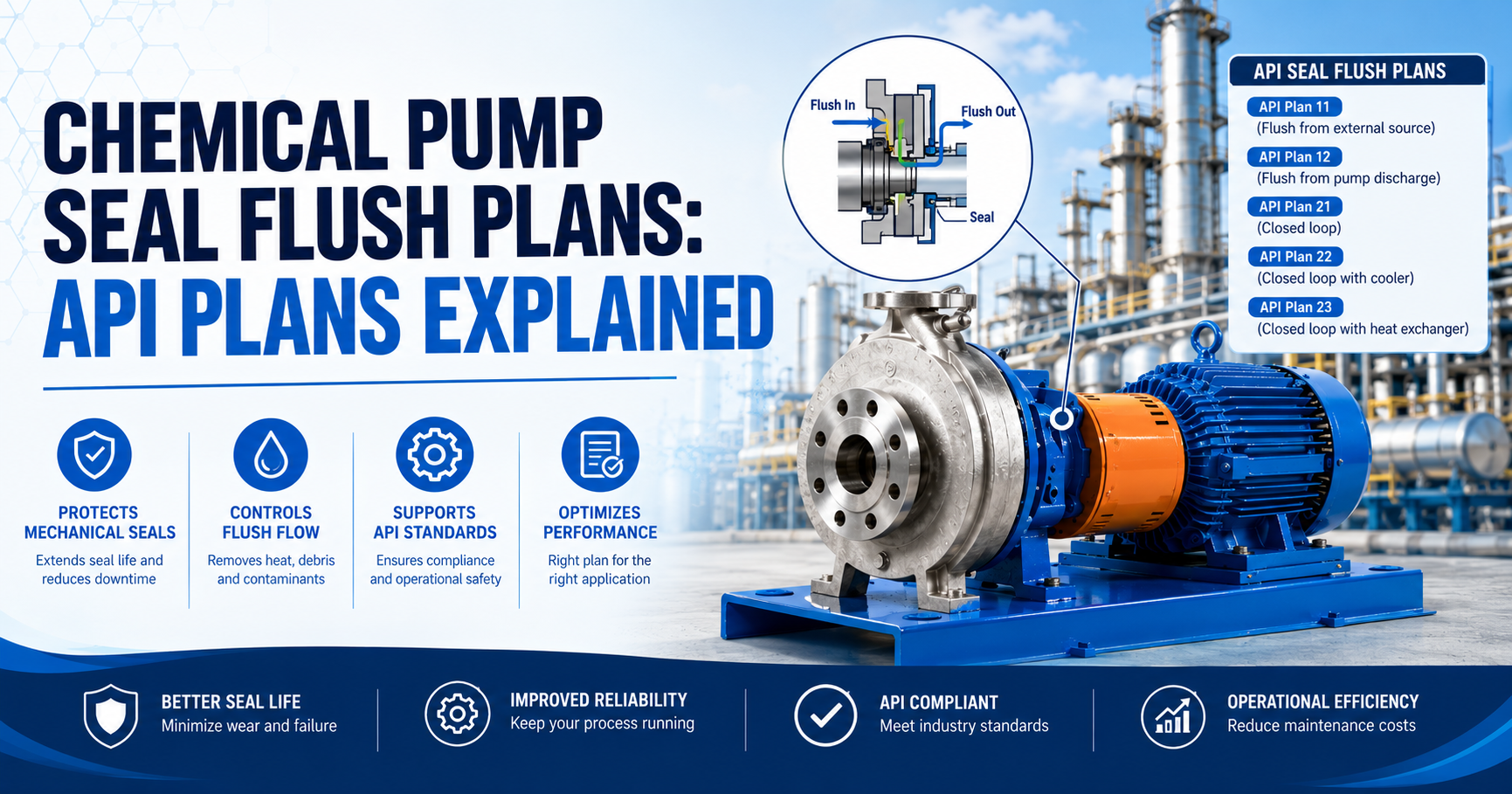
A seal flush plan is a standardised piping arrangement that conditions the environment around a mechanical seal — cooling it, cleaning it, or supplying a buffer or barrier fluid. The right plan keeps seal faces lubricated and within temperature limits. The wrong one shortens seal life and, on a chemical pump, turns a seal failure into a chemical leak.
A mechanical seal does not survive on its own material selection. It survives on the environment it runs in. Give it clean, cool, pressurised fluid at the seal faces and it will run for years. Expose it to hot vapour, abrasive particles, or a fluid it was never designed to handle, and it fails — often quickly, and in chemical service, dangerously.
That is what a seal flush plan does. It controls the environment at the seal faces by managing what fluid reaches them, how much pressure surrounds them, and how much heat is removed from them. The American Petroleum Institute standardised these arrangements in API 682, which is why they are called API plans. Most industrial chemical pumps — not just oil and gas applications — specify flush plans from this standard because it provides a common language between pump manufacturers, seal suppliers, and plant engineers.
This guide covers the most commonly used API flush plans for chemical pump service, explains what each one does and when to use it, and maps common chemical applications to the plan that fits them.
For background on the seal types these plans support, see our mechanical seals for chemical pumps guide. For material compatibility guidance before specifying a flush plan, see our chemical pump material compatibility guide.
Why Mechanical Seals in Chemical Pumps Need a Flush Plan
A mechanical seal creates a very thin liquid film between its rotating and stationary faces. That film does two things: it lubricates the faces so they do not wear against each other, and it carries away the heat generated by the small amount of face contact that occurs during operation.
Take away that film — by running the pump dry, by allowing the fluid in the seal chamber to vapourise, or by allowing solids to accumulate between the faces — and the seal overheats, the faces crack or warp, and leakage follows.
In a standard water pump, the fluid itself usually provides adequate lubrication and cooling without any additional arrangement. In a chemical pump, four conditions make that inadequate:
- High temperature. Some process chemicals run hot enough that the fluid in the seal chamber approaches its vapour pressure, forming vapour pockets that disrupt the liquid film. The seal runs partially dry.
- Abrasive or solid-bearing fluids. Particles in the process fluid accumulate between the seal faces and cause accelerated wear.
- Polymerising or crystallising chemicals. Some fluids solidify or crystallise when they are exposed to lower pressure and temperature at the seal faces, building up deposits that mechanically force the faces apart.
- Hazardous chemicals. When any leakage at the seal is unacceptable — because the chemical is toxic, flammable, or strictly regulated — a single seal with a process fluid flush is not enough. A second seal and a barrier fluid are required.
Each of these conditions calls for a different flush plan.
How API Flush Plans Are Numbered
API 682 organises flush plans by number. The number does not follow a simple logical sequence — it is a historical convention — but the plans group into three families based on what they do:
| Family | Plans | What They Do |
|---|---|---|
| Single seal flush plans | 11, 13, 21, 23, 31, 32, 41 | Condition the process fluid or replace it with a clean flush around a single seal |
| Dual seal buffer plans | 52, 72 | Provide an unpressurised buffer fluid between the faces of a tandem (dual unpressurised) seal |
| Dual seal barrier plans | 53A, 53B, 53C, 54 | Provide a pressurised barrier fluid between the faces of a double (dual pressurised) seal |
This guide focuses on the five plans that cover the majority of chemical pump applications: Plans 11, 21, 32, 52, and 53A. Plans 13, 23, 31, 41, and others exist for specific situations — vertical pumps, hot water service, cyclone separation — but are less commonly specified in general chemical process service.
Plan 11 — The Default Single Seal Flush
What it does: Routes a portion of the pump’s discharge flow through a restriction orifice into the seal chamber, then allows it to rejoin the process stream. The pressurised discharge flow continuously flushes the seal chamber, carries away heat, and maintains a positive pressure that prevents vapour formation at the faces.
How it works in practice: A small tapping on the pump discharge nozzle connects to an orifice and then to the flush port on the seal chamber. The orifice controls flow rate. The discharged flush fluid mixes back into the process at a downstream point or simply circulates within the pump.
Use it when:
- The process fluid is clean or only mildly contaminated
- The fluid does not approach its vapour pressure at seal chamber conditions
- Temperature is moderate — below about 120°C for most chemical service
- The fluid is compatible with the seal faces and elastomers at the operating concentration and temperature
Do not use it when:
- The process fluid is abrasive or carries solids — recirculating that fluid over the seal faces accelerates wear
- The fluid polymerises, crystallises, or solidifies at the slightly lower temperature and pressure of the seal chamber
- The fluid temperature is high enough to approach its vapour pressure in the seal chamber
- Any leakage at the seal is unacceptable
Plan 11 is the starting point for most general chemical transfer applications in clean service. If you are pumping a clean acid, caustic, or aqueous chemical at moderate temperature and the fluid is compatible with the seal, Plan 11 is usually sufficient.
Plan 21 — Single Seal Flush With Cooling
What it does: Identical to Plan 11 except that the recirculated discharge flow passes through a heat exchanger before entering the seal chamber. The cooler reduces the temperature of the flush fluid before it reaches the seal faces.
Use it when:
- Plan 11 alone cannot hold the seal chamber temperature below the seal’s rated limit
- The process fluid is clean but runs at elevated temperature
- You need slightly more cooling capacity than a simple recirculation orifice provides, but the fluid itself is still suitable for face lubrication
The limitation: The heat exchanger adds a maintenance item — it needs to be kept clean and the cooling water supply confirmed active. In chemical service, a cooler that scales up or blocks on the process side reduces the temperature benefit rapidly.
For most ANSI chemical process pumps in moderate-temperature acid, caustic, or general chemical service, Plan 11 is the more common choice over Plan 21. Plan 21 is more frequently specified in higher-temperature applications such as hot process chemical service or elevated-temperature caustic lines.
Plan 32 — External Clean Flush Injection
What it does: Injects a clean, compatible flush fluid from an external source into the seal chamber at a controlled flow rate and pressure higher than the seal chamber pressure. The external flush replaces the process fluid at the seal faces entirely — the faces see only the clean flush fluid, not the process chemical.
Use it when:
- The process fluid is abrasive, carries solids, or would damage seal faces if recirculated
- The fluid polymerises or crystallises at the seal faces
- The fluid is incompatible with available seal face materials but a compatible flush fluid exists
- The process fluid is at very high temperature and an external cool flush is more practical than recirculation with cooling
The critical requirement: The external flush fluid must be:
- Compatible with the process chemical — it will contaminate the product at a low level
- At a higher pressure than the seal chamber to ensure inward flow (flush into the process, not process into the flush line)
- Clean and free of solids
- Available at a reliable, uninterrupted supply pressure
In chemical plant practice, a clean solvent compatible with the process, deionised water, or a dilute version of the process fluid are common Plan 32 flush sources for acid and caustic chemical pumps where the process fluid itself is unsuitable for face lubrication.
Plan 32 is the right answer for abrasive chemical slurries, polymerising chemicals, and any application where the process fluid would damage the seal faces on recirculation. It is commonly paired with the chemical process pump range on aggressive chemical service.
Plan 52 — Unpressurised Buffer Fluid for Tandem (Dual) Seals
What it does: Supplies a buffer fluid — an unpressurised liquid held in an external reservoir — to the cavity between the two seal faces of a tandem (dual unpressurised) seal arrangement. The inner seal faces the process. The outer seal faces the buffer fluid. The buffer fluid is at a pressure lower than the process, so any leakage is inward — process fluid leaks into the buffer fluid reservoir, not out to atmosphere.
Use it when:
- Leakage of the process fluid to atmosphere must be contained and monitored, but a small amount of inward leakage into the buffer reservoir is acceptable
- The chemical is moderately hazardous — requires containment and leak detection, but not absolute zero-leakage
- Regulatory requirements demand leakage monitoring with the option to detect inner seal failure before atmospheric release
- You need a safety backup that contains leakage if the inner seal fails
How to monitor it: A level indicator and pressure gauge on the buffer reservoir tell you when the inner seal is leaking — the reservoir level rises as process fluid enters it. Many installations also include a reservoir level alarm that triggers when inner seal leakage exceeds a set volume.
Plan 52 vs. Plan 53 — the key difference: In Plan 52, the buffer fluid pressure is lower than the process pressure. Leakage runs inward. In Plan 53, the barrier fluid pressure is higher than the process pressure. Leakage runs outward — from the barrier fluid into the process — which means no process fluid ever reaches the outboard seal face or atmosphere. When zero atmospheric leakage is the requirement, Plan 53 is correct, not Plan 52.
Plan 53A — Pressurised Barrier Fluid for Double (Dual) Seals
What it does: Pressurises a barrier fluid in an external reservoir to a level above the seal chamber pressure, then circulates it through the cavity between the two seal faces of a double (dual pressurised) seal arrangement. Because barrier fluid pressure exceeds process pressure, the net leakage direction is from barrier fluid into the process — not from the process to atmosphere. The process chemical never contacts the outboard seal face or atmosphere.
Use it when:
- Zero leakage of process fluid to atmosphere is required — the chemical is toxic, flammable, carcinogenic, or strictly regulated
- Environmental compliance requirements prohibit any atmospheric release of the process chemical
- OSHA 29 CFR 1910.119 process safety management requirements apply to the chemical being pumped
- The inner seal alone cannot reliably contain the chemical under all operating conditions
The barrier fluid: Must be compatible with both the process chemical (it will enter the process at the inner seal) and the seal elastomers and faces. Typical barrier fluids for chemical service include clean compatible process fluid, deionised water, mineral oil, and glycol solutions depending on the chemical being pumped and the temperature.
Plan 53A in practice: A nitrogen-pressurised accumulator maintains the barrier fluid reservoir above process pressure. A pumping ring or external pump circulates barrier fluid through the dual seal cavity. Pressure and level instrumentation on the reservoir monitors barrier fluid consumption — sustained high consumption indicates inner seal wear. The dual cartridge seal with pumping ring in Rotech’s range, the RSCD2PR, is designed specifically for Plan 52 and 53A arrangements.
For the most hazardous chemical applications — concentrated acids, chlorinated solvents, toxic process chemicals — Plan 53A with a double seal is the standard specification. Single seals with any flush plan are not adequate when zero atmospheric leakage is the requirement.
Choosing the Right Flush Plan: A Decision Framework
Work through these four questions in order:
1. Is any leakage of the process chemical to atmosphere acceptable?
No — the chemical is toxic, flammable, or regulated: → You need a double (dual pressurised) seal and Plan 53A
Leakage must be contained and monitored but a small amount inward is acceptable: → Tandem (dual unpressurised) seal with Plan 52
Yes — leakage to atmosphere in small amounts is acceptable for this chemical: → Continue to Question 2
2. Is the process fluid suitable to circulate over the seal faces?
No — it is abrasive, carries solids, polymerises, or crystallises at the faces: → Plan 32 (external clean flush)
Yes — the fluid is clean and would not damage the faces: → Continue to Question 3
3. Is temperature a concern at the seal chamber?
Yes — the fluid approaches its vapour pressure in the seal chamber at operating temperature, or the seal’s temperature limit would be exceeded with simple recirculation: → Plan 21 (recirculation with cooler)
No — temperature is within the seal’s rated range with simple recirculation: → Plan 11 (standard recirculation)
4. Is the pump vertical?
For vertical pumps, Plan 11 alone is generally not used because the recirculation line may not remain full. Plan 13 (recirculation from seal chamber to suction) or Plan 14 (combined 11 and 13) are the standard for vertical configurations. This applies to Rotech’s vertical centrifugal pump and RVI80 vertical inline range.
Flush Plan Selection by Chemical Service
| Chemical | Typical Flush Plan | Reason |
|---|---|---|
| Sulfuric acid (clean, moderate temp) | Plan 11 | Clean fluid, moderate conditions — standard recirculation adequate |
| Sulfuric acid (hot or concentrated) | Plan 32 | Hot concentrated acid may approach vapour pressure or be incompatible with face recirculation at high concentration |
| Hydrochloric acid | Plan 32 | HCl vapour at faces causes accelerated face wear — external clean flush keeps faces away from HCl vapour |
| Caustic soda (NaOH, clean, moderate) | Plan 11 | Clean fluid compatible with standard seal faces and elastomers |
| Caustic soda (hot, concentrated) | Plan 21 | Elevated temperature needs additional cooling |
| Sodium hypochlorite | Plan 32 | Oxidising nature and chloride content are aggressive to seal faces — external flush protects faces |
| Nitric acid | Plan 11 or 32 | Plan 11 for dilute at ambient; Plan 32 where concentration or temperature is higher |
| Phosphoric acid with solids | Plan 32 | Solids in phosphoric acid slurry damage faces on recirculation — external clean flush mandatory |
| Toxic or regulated chemicals | Plan 53A | Zero atmospheric leakage required — double seal with pressurised barrier |
| Flammable solvents | Plan 53A | Zero atmospheric leakage; flammability risk eliminates single seal options |
| Acetic acid (glacial) | Plan 32 | Glacial acetic acid at the faces can cause build-up — external flush prevents face deposits |
What Changes With the Flush Plan Selection
Specifying a flush plan is not just a piping decision. It changes what seal type you need, what instrumentation you require, and what your maintenance programme looks like.
Single seal plans (11, 21, 32) work with single mechanical seals. For chemical service, the right single seal type depends on pressure, temperature, and chemical compatibility. Browse Rotech’s elastomer bellow seals, PTFE bellow seals, balanced seals, and cartridge seals for single seal options across the full range of chemical conditions.
Dual seal plans (52, 53A) require a dual seal arrangement — either tandem (unpressurised) for Plan 52 or double (pressurised) for Plan 53A. These are more complex to install and maintain than single seal arrangements. The RSCD2PR dual cartridge seal is designed for Plan 52 and 53A service, with an integrated pumping ring for barrier or buffer fluid circulation.
Instrumentation requirements increase with plan complexity. Plan 11 needs no instruments — just an orifice and piping. Plan 32 needs a flow indicator or rotameter on the flush supply. Plan 52 needs a level indicator and pressure gauge on the reservoir, usually with a high-level alarm. Plan 53A adds a pressure transmitter and often a flow indicator on the barrier fluid circulation loop.
Flush Plan Maintenance
A correctly installed flush plan reduces seal maintenance requirements. An incorrectly maintained flush plan causes the seal failures it was installed to prevent.
Plan 11 and 21: Confirm the orifice is not blocked during routine maintenance. A blocked orifice stops flush flow and allows the seal chamber temperature and pressure to drift — the seal starts running in degraded conditions without any visible sign until it fails. For Plan 21, confirm cooler flow and outlet temperature at each inspection.
Plan 32: Confirm external flush supply pressure exceeds seal chamber pressure at all operating conditions, including during startup and shutdown transients when process pressure may spike. Confirm flush flow rate at the rotameter. Any interruption in Plan 32 flush supply means the seal is running on process fluid — which may be immediately harmful to the faces.
Plan 52: Check reservoir level and pressure at regular intervals. Any sustained rise in reservoir level means the inner seal is leaking process fluid into the buffer — a sign the inner seal needs inspection or replacement before the outer seal is asked to contain the leakage alone.
Plan 53A: Monitor barrier fluid pressure and consumption. A sustained rise in consumption means barrier fluid is leaking into the process — the inner seal is wearing. Confirm nitrogen supply pressure to the accumulator at every inspection.
For the full chemical pump maintenance schedule, including seal-specific inspection intervals, see our chemical pump maintenance tips guide. For diagnosing problems when a flush plan is not performing as expected, our chemical pump troubleshooting guide covers the diagnostic approach for seal and flush system failures.
Frequently Asked Questions
What is an API seal flush plan? An API seal flush plan is a standardised piping arrangement, defined in API 682, that conditions the environment around a mechanical seal — supplying flush fluid, cooling, buffer fluid, or pressurised barrier fluid to the seal faces. The plan number tells engineers, seal suppliers, and pump manufacturers exactly how the seal system is piped without needing a full drawing for every installation.
What is the most common seal flush plan for chemical pumps? Plan 11 is the most widely used — a simple recirculation from pump discharge through an orifice to the seal chamber. It suits most clean chemical transfer applications at moderate temperature and pressure. For more aggressive or hazardous chemicals, Plan 32 (external clean flush) or Plan 53A (pressurised barrier fluid with double seal) are the common alternatives.
What is the difference between Plan 52 and Plan 53? Both support dual seal arrangements, but the pressure relationship is opposite. Plan 52 supplies an unpressurised buffer fluid at a pressure lower than the process — leakage runs inward, from process into the buffer. Plan 53A supplies a pressurised barrier fluid above the process pressure — leakage runs from barrier fluid into the process, so no process fluid ever escapes to atmosphere. Plan 53A is required when zero atmospheric leakage is the specification.
When should I use Plan 32 instead of Plan 11? Use Plan 32 when the process fluid is unsuitable for recirculating over the seal faces — because it is abrasive, carries solids, polymerises, crystallises at lower seal chamber conditions, or is at a temperature and concentration that makes recirculation harmful. Plan 32 replaces the process fluid at the faces entirely with a clean external flush.
Does every chemical pump need a flush plan? No. Simple single seal configurations on clean chemical service at moderate temperature often run without a dedicated flush plan — the pump’s own fluid circulation provides adequate face lubrication. A flush plan becomes necessary when the process conditions are harsh enough that the default lubrication is inadequate, or when regulatory or safety requirements demand containment and monitoring.
What fluid is used in Plan 53A? The barrier fluid must be compatible with both the process chemical (it will enter the process at the inner seal faces) and the seal elastomers and face materials. Typical choices include clean compatible process fluid, deionised water, mineral oil, or glycol solutions, depending on the chemical service, temperature, and seal materials.
Can I retrofit a flush plan to an existing chemical pump? Yes, in most cases. The pump needs the correct flush ports on the seal chamber — most ANSI and chemical process pump designs include these as standard tappings. The piping, orifice, cooler (if Plan 21), or external reservoir system (if Plan 52 or 53A) are added externally. Confirm the existing seal is rated for the operating conditions and compatible with the flush fluid before retrofitting.
How do I know if my flush plan is working? For Plan 11 — check that the orifice is clear and that the seal chamber temperature is within the seal’s rated range during operation. For Plan 32 — confirm flush supply flow at the rotameter and check that supply pressure exceeds chamber pressure. For Plan 52 — check reservoir level trend; a rising level means inner seal leakage. For Plan 53A — check barrier fluid pressure and consumption trend.
Summary
A seal flush plan is not an optional add-on to a chemical pump mechanical seal. It is part of the seal system — the piping arrangement that determines whether the seal survives its operating conditions or fails prematurely.
Plan 11 covers most clean chemical service at moderate temperature. Plan 32 is the answer when the process fluid itself would damage the faces. Plan 52 provides contained leakage monitoring for moderately hazardous chemicals. Plan 53A is the specification when zero atmospheric leakage is required.
Getting the plan right before installation costs nothing beyond the correct piping and orifice. Retrofitting a more appropriate plan after the first seal failure — in chemical service — costs the replacement seal, the downtime, the process disruption, and in the worst case a chemical release that should never have happened.
At Rotech Pumps, our mechanical seal range and seal flush plan accessories cover the full range of single and dual seal arrangements for chemical pump service across the USA and Canada. If you are specifying a flush plan for a new installation or evaluating an existing arrangement that is not performing, contact our engineering team or submit a pump inquiry with your chemical, temperature, and pressure conditions.
Recent Posts
Chemical Pump Seal Flush Plans: API Plans Explained
A seal flush plan is

What Is a Chemical Metering Pump? Types, How They Work, and How to Size One
A chemical metering pump is

Centrifugal Pump Installation Guide: Step-by-Step Best Practices
A centrifugal pump installation has